Time Globe
A glimpse of the present
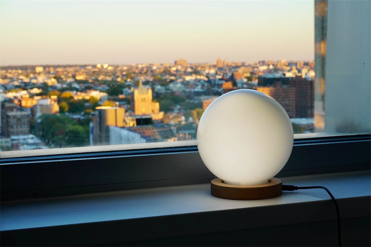
Because the earth is a sphere, the sun only illuminate half of it. ‘Time Globe’ is a lamp and also a clock that shows the time by the angle of the illuminated part. It makes a full turn once a day representing the sun shining at the earth. There is also different modes for other planets so you can have a sense of living on another planet.
Sketch & Prototype
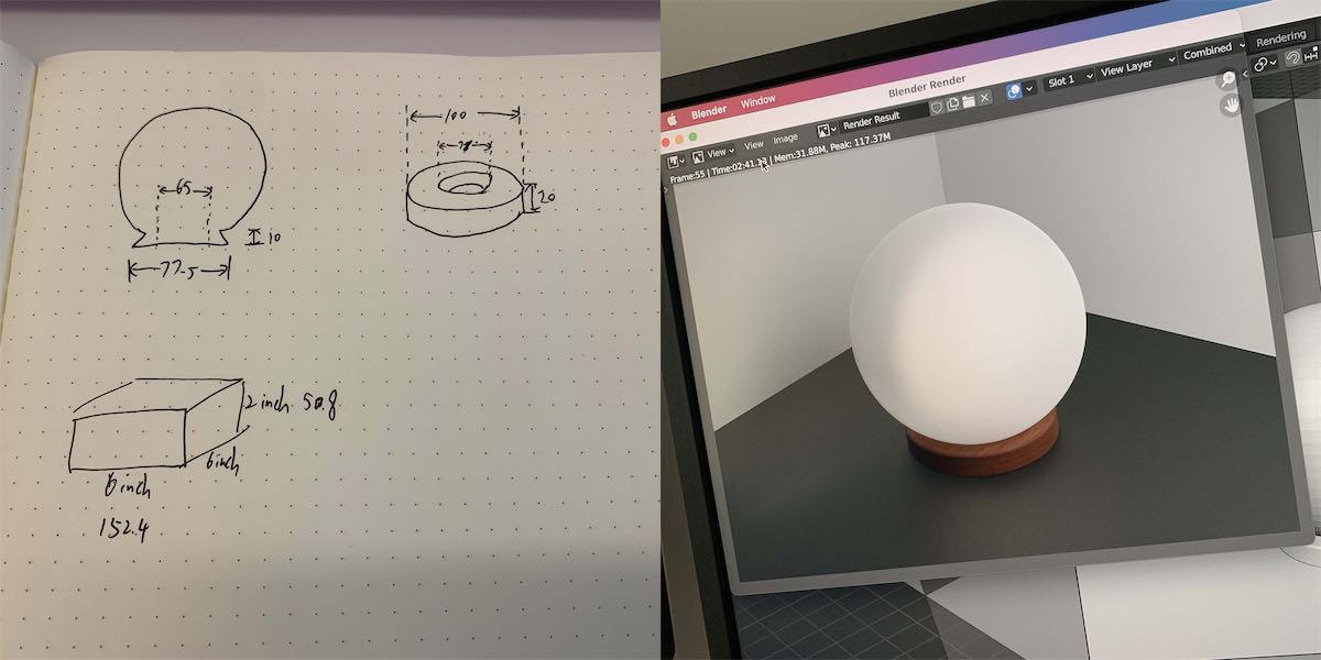
I first draw some sketch and did a model of the lamp. I found globe glass shade a perfect fit for this project so I ended up bought one from amazon.
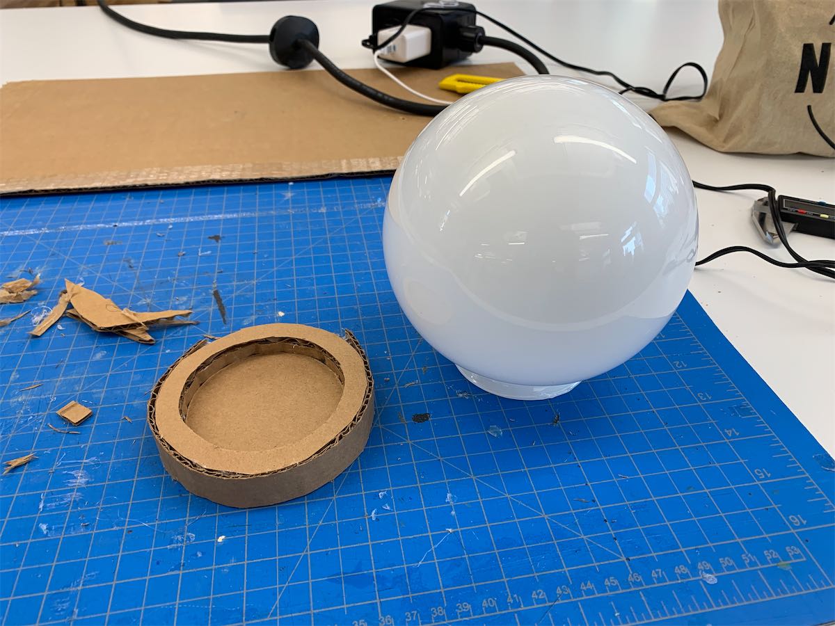
Than I made a cardboard base for prototype. It is a cylinder with a pocket that connects the globe. The base would later be remake with white oak for a better finish look.
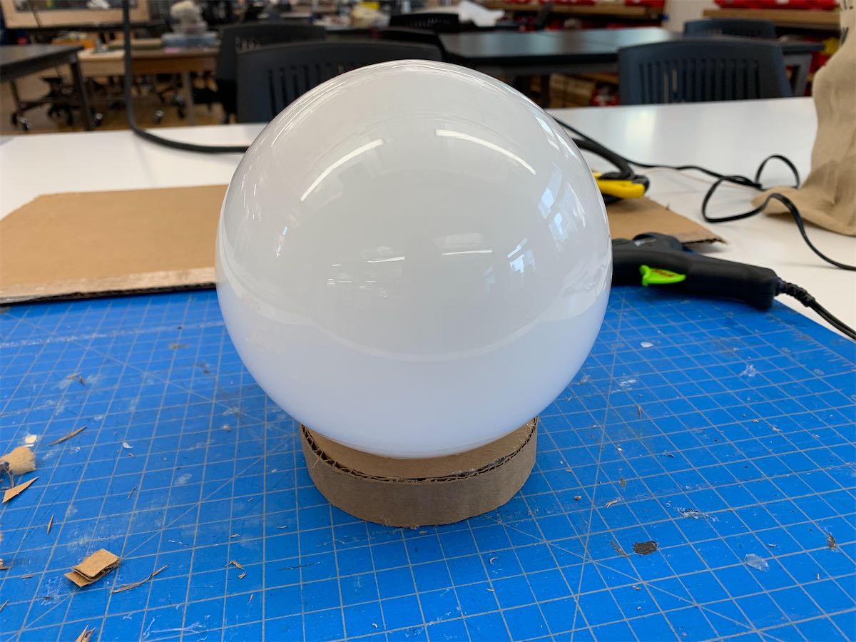
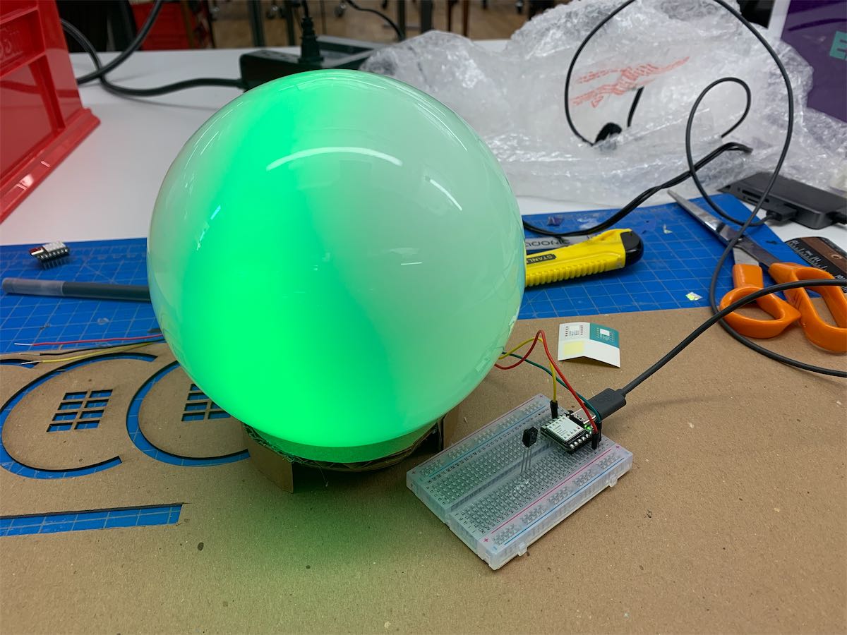
The shade blend the light pretty good and creates this amazing gradient.
Mechanism
There are two ways of making the light rotate, either digitally or physically. I initially went for the digital plan since it offered more dynamic and organic control. My idea was to make a whole LED globe and control the on/off and color for each of them, therefore make the whole globe part-illuminated. I also found some existing example that works and looks nice, but the problem is I need them to fit in the very small entrance hole which is almost impossible to implement.
Instead, A physical plan seems much more executable. Some attributes that needs to be controlled are:
- Rotation - by a stepper motor
- Tilt - by a servo motor (or digitally?)
- Color (Pattern) - by led strip / matrix
I also went through some prototype for the led strip. My first attempt was to make a part-circle, so each one is having the same distance to the globe shade. The reason I choose to make it over 180 degree is because I was thinking about controling the tilt of the light digitally. I’m not feeling confident adding a servo.
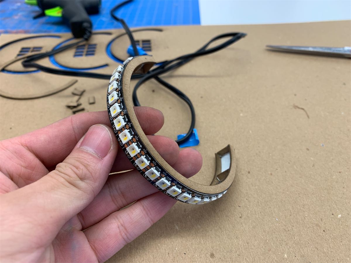
Sadly, it didn’t work and created this cool-but-weird effect. So I believe going physical is the only way.
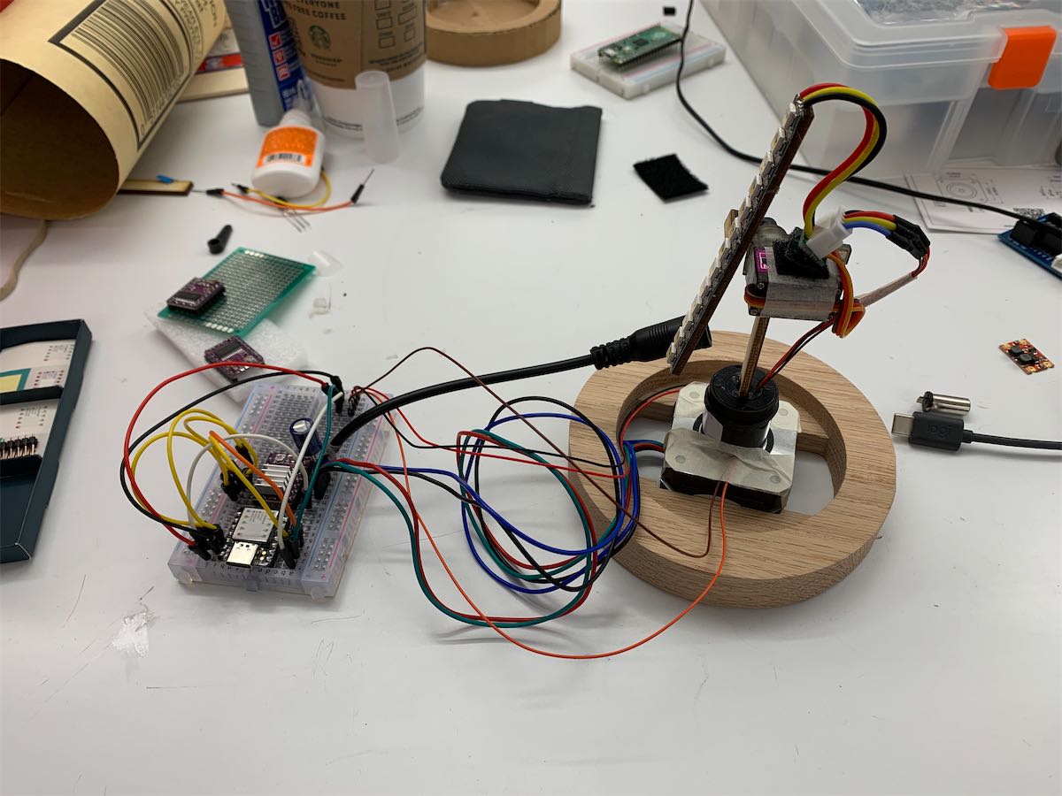
Therefore, my second attempt was a straight line of LED. A MG90S servo is added to create the tilt effect.
Having a 360 degrees infinity spining part is hard
Later I noticed a huge problem. While the LEDs and servo are rotating 360 degrees infinitely, they still need to connect to the power and control signal which is stationary. Thus the wire between them will be tangled inevitably.
With the help of Jeff, I realized I need a slip ring which can rotate freely while retaining good contact with multiple wires.
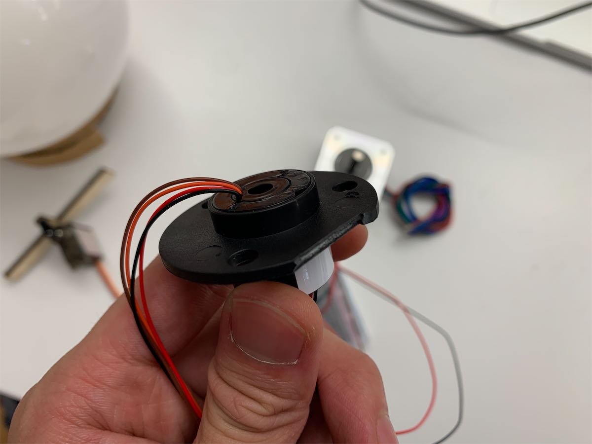
Isn’t it beautiful? Everything is working now and it’s time to do the fabrication.
Fabrication
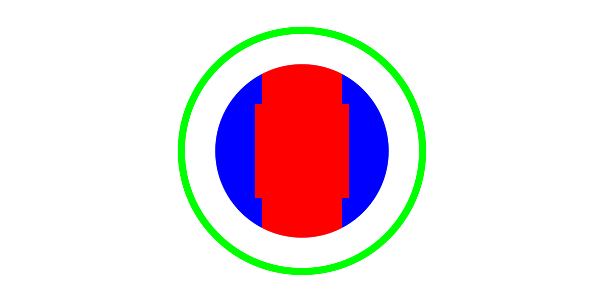
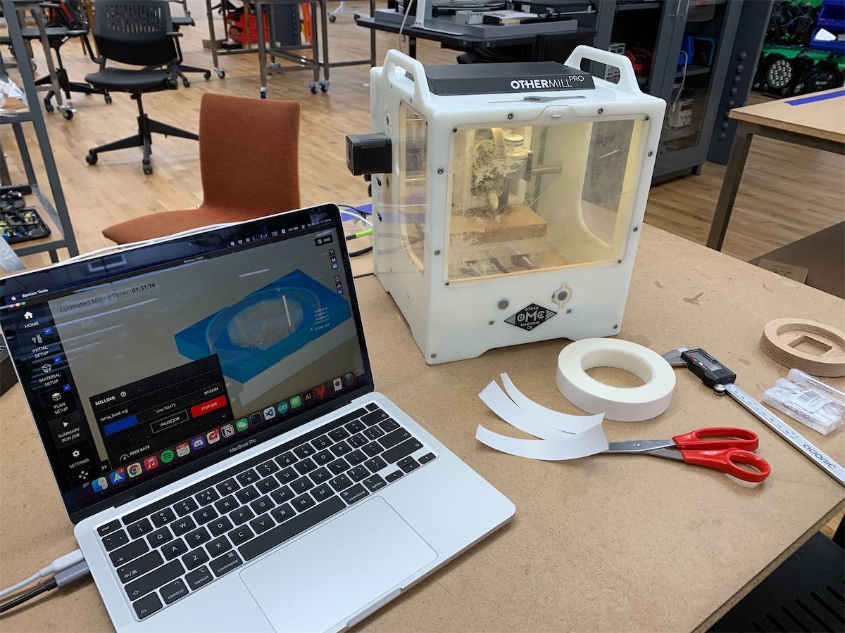
Since the globe part is already purchased from amazon, it would be mainly about fabricating the base. Many thanks to Lulu for helping me with the CNC machine. It was my first time, so I went for the SVG workflow.
The blue part is an 1cm engrave connect to the globe shade and the red part is reserved for holding the stepper motor and other electronics.
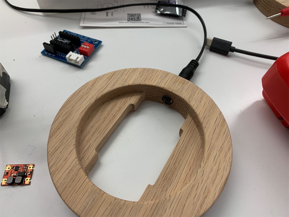
After the milling process, I sanded the whole thing with 220 grit sandpaper and drilled a hole for the power port. A layer of wax paste is also applied to the base for a smooth and natural look.
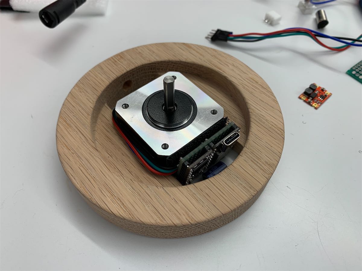
My last challenge was to put all the stuff in the base while still maintaining a clean look. Hope I have planed enough space.
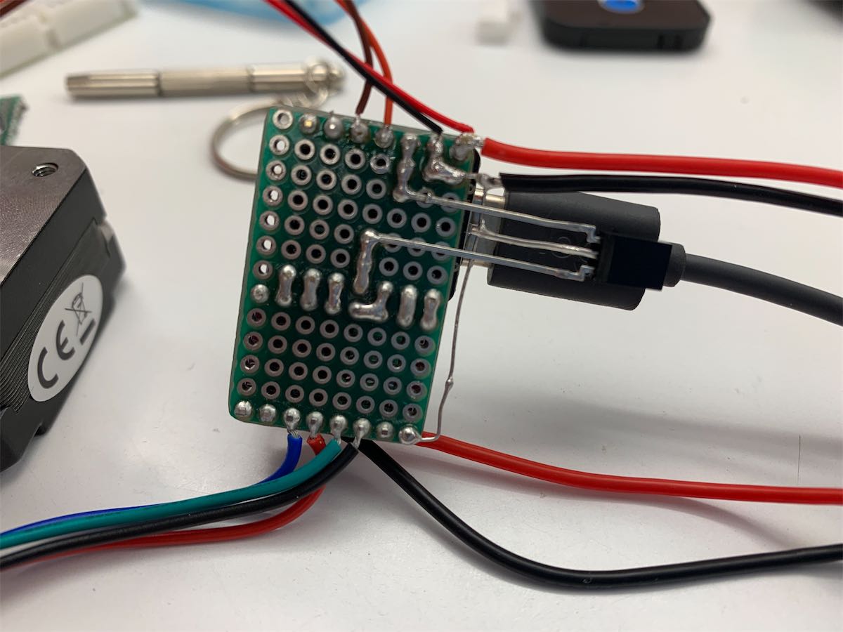
I tried my best to put all the things on a small protoboard. Luckily, it didn’t fail me. I have to remove the heat sink for the stepper motor driver, but it’ll probably be fine. One Seeeduino XIAO also bricked for an unknown reason, so I have to redo all the things again. Then everything started to come together.
Here are the final testing video for both with shade and without shade.
Software
For now, I only created 5 mode:
- Earth in real-time - (not work)
- Earth (for presentation)
- Venus (for presentation)
- Jupiter (for presentation)
- Neptune (for presentation)
The parameters of each mode are stored in several constant array. These specific planets are selected for demonstrating their special behavior (e.g. Venus spins in a different direction compares to the rest).
// https://en.wikipedia.org/wiki/Axial_tilt
// Earth (real-time) / Earth (present) / Venus / Jupiter / Neptune
const unsigned int milPerStep[NUM_OF_MODE] = {13500, 4, 8, 1, 2};
const unsigned int maxTilt[NUM_OF_MODE] = {66, 66, 7, 9, 80};
const bool rotateDir[NUM_OF_MODE] = {HIGH, HIGH, LOW, HIGH, HIGH};
const uint32_t oneColor[NUM_OF_MODE] = {0x01000000, 0xaa000000, 0x00d1bda9, 0x00a35f31, 0x001757cc};
Although all the presentation modes are working. In real-time mode, the light doesn’t spin at all. It seems like the stepper motor won’t move as usual when the distance between the two steps are too far. I still need to figure it out
Resources
The code haven’t been finalized yet, but you can check the current one here.